Equations and Calculations related to Resistance Welding
Welding Related Math
These are some of the basic calculations you should become familiar with if you are shopping for equipment or learning about the resistance welding process.
Time calculations
Weld Cycles
The first resistance welders were tied to the utility frequency of the power supply to the machine. For this reason, you will still see Weld Cycles quite commonly in resistance welding documentation. In North America, line frequency is 60Hz. In many other parts of the world, utility frequency is 50Hz.

World map showing frequency for public mains power, by country. Not all colored areas have mains power available. Japan uses both 50Hz and 60Hz.
Single-phase AC machines still count the number of cycles of the utility frequency to control the time of a weld. Inverters (sometimes called Mid-Frequency Direct Current [MFDC] welders) are often 1000Hz frequency, which makes the time calculations easier.
Weld time (in milliseconds) = number of weld cycles / utility frequency
In North America, with 60Hz:
Weld time (in milliseconds) = number of cycles / 60
example
15 cycles of weld time
Weld time (in milliseconds) = 15 / 60 = 0.250 seconds (or 250milliseconds [ms])
In England and Europe, China, and most other places in the world with 50Hz:
Weld time (in milliseconds) = number of cycles / 50
example
15 cycles of weld time
Weld time (in milliseconds) = 15 / 50 = 0.300 seconds (or 300milliseconds [ms])
Duty Cycle
Duty Cycle is used to mathematically derate a welding transformer. Resistance welders very rarely operate at 100% duty cycle (which equates to being on all the time, like a light bulb). They are often turned on for only brief periods of time. If all resistance welders were sized at 100% duty cycle, they would all be enormous and very expensive. Therefore, Duty Cycle can be used to make equipment more suitable for everyday “normal” operations.
Care must be taken when shopping for a welder, as Duty Cycle calculations can be manipulated to make machinery sound more powerful than other equipment. See charts below in “KVA as a Function of Duty Cycle” section. “50KVA” is not always an apples-to-apples comparison.
In North America, it is generally standard to rate welding transformers at 50%. On some imported equipment, you will see Duty Cycle ratings of 20%. One may find transformers rated as low as 4%. (A transformer rated at 0% means you could never use it.)
Duty Cycle = (weld time on) / (elapsed time)
elapsed time is often calculated using 2-seconds, but can also be calculated over one minute
example (1 minute)
averaging 4 welds per minute with a weld time of 15 cycles (250ms) in North America
Duty Cycle = (4 welds X 0.250sec) / 60sec = 0.01667 = 1.67% duty cycle
example (2 seconds)
averaging 1 weld per 2 seconds with a weld time of 15 cycles (250ms) in North America
Duty Cycle = (1 welds X 0.250sec) / 2sec = 0.125 = 12.5% duty cycle
Transformer KVA
Single Phase Amps to kVA calculation
S (kVA) = I (A) x V (RMS) / 1000
S (kVA) = apparent power in kVA
I (A) = current, in amps
V (RMS) = rms voltage
example
I (A) = 153 A
V (RMS) = 460 V
S (kVA) = 70 kVA
Three (3) Phase Amps to kVA calculation
S (kVA) = sqrt(3) x I (A) x V (RMS) / 1000
S (kVA) = apparent power in kVA
I (A) = current, in amps
V (RMS) = rms voltage
example
I (A) = 153 A
V (RMS) = 460 V
S (kVA) = 122 kVA
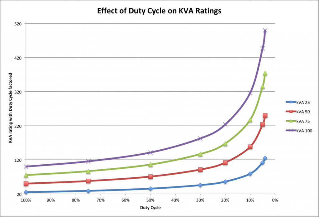
KVA as a Function of Duty Cycle
Px = Pmax X sqrt(Dc)
Px = KVA(x%Duty)
Pmax = KVA(100%Duty)
Dc = Duty Cycle (example: 30%=0.30)
example
Dc= 0.5
Pmax= 100 KVA
Px = 70.7 KVA
example
Dc= 0.5
Px = 100 KVA
Pmax= 141.4 KVA
![]()
Turns Ratio
Turns Ratio is simply the ratio of the input voltage/amperage to the output voltage/amperage.
The Power into a transformer should be roughly the same going in as going out. Therefore:
Power (in) = Power (out)
and
Power (Watts) = Volts X Amps
Volts (in) X Amps (in) = Volts (out) X Amps (out)
Volts (in) / Amps (out) = Volts (out) / Amps (in)
Example: If you supply 480V to your spot welder, and the welder outputs 9V on the secondary:
480V / 10V = 48:1 turns ratio.
With a single-phase AC transformer, you can apply a known voltage to the primary side (like 120VAC), measure the secondary Volts, and then determine your transformer turns ratio.
Primary Amps, Given Secondary Amps and Turns Ratio
If you have a resistance welding current meter (or your weld control tells you your secondary current), and you know your Turns Ratio on your transformer (often listed on the transformer tag as well), you can determine your primary Amps (coming into the machine).
First determine your Secondary Current, using a Current Meter or current-sensing weld controller. Then determine your Turns Ratio (per above). Know that, on an Inverter-style spot welder, the incoming voltage to the transformer is likely higher than the supplied voltage. A traditional 1000Hz Inverter has 650VAC with 480VAC supply, for example.
PRIMARY AMPS, Single Phase
Amps Secondary = A(secondary)
Amps Primary = A(primary)
A(primary) = A(secondary) / Turns Ratio
Example:
A(secondary) = 25kA = 25000A
Turns Ratio = 72
A(primary) = A(secondary) / Turns Ratio
A(primary) = 25000 / 72 = 347A
Your welder needs 347A
PRIMARY AMPS, Three Phase
The three-phase formula is the same, except with an inverter, you must multiply by a constant of 0.81 for 3-phase distribution.
Amps Secondary = A(secondary)
Amps Primary = A(primary)
A(primary) = [ A(secondary) * (0.81) ] / Turns Ratio
Example:
A(secondary) = 25kA = 25000A
Turns Ratio = 72
A(primary) = A(secondary) * (0.81) / Turns Ratio
A(primary) = 25000 * 0.81 / 72 = 347A * (0.81) = 281A
Your welder needs 281A